LLRF9/476 Demonstration at SPEAR3
 On June 24th, 2014, LLRF9/476 was demonstrated ANKA storage ring. Complete LLRF system setup included:
- Calibration of six RF signals (probe, forward and reflected for two cavities);
- Setup of excessive power and voltage interlocks;
- Closed-loop resonant frequency control (with tuner motor control via EPICS2ACS gateway);
- Two cavity vector sum setup;
- Feedback loop tuning;
- Interface to ANKA control system to support station voltage ramping during energy ramp.
Complete setup took less than 7 hours from unpacking the LLRF9/500 unit to injecting beam.
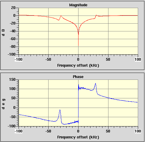
The plot on the right shows closed-loop disturbance rejection transfer function measured from the setpoint input to the loop error signal (difference between the setpoint and the cavity vector sum). This measurement was performed with beam and shows both cavity response, modified by feedback loops, and longitudinal beam response (around 30 kHz offsets). Low-frequency disturbance rejection is around 15 dB at 10 kHz, increasing to more than 70 dB at 27 Hz.