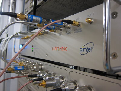
LLRF9
LLRF9 is a 9-channel low-level RF controller, designed for lepton storage rings and boosters. LLRF9 supports multiple RF station configurations, with one or two high-power sources (klystron, IOT, solid-state amplifier) and one or two RF cavities. Controller performs vector summing of cavity probe signals, then uses low-latency proportional and integral loops to stabilize the amplitude and phase of the vector sum. Feedback loops are optimized to achieve fast transient response as well as good rejection of perturbations in steady-state operation. Station voltage and phase setpoint can be ramped or modulated using 512 point arbitrary profiles. Profile ramping can be triggered in software or by external opto-isolated trigger inputs. Adjustable time per step allows one to achieve transient profiles from 70 μs to 18.7 s.
LLRF9 includes integrated fast input interlocks, acting on excessive input amplitude. Nine interlock sources are combined in hardware with an opto-isolated external interlock input. Resulting signal is used to turn off klystron drive and is also available as hardware output for interlock daisy-chaining. All interlock sources are timestamped with ±17.4 ns uncertainty, with automated event sequencing in EPICS.
System supports multiple mechanical tuner motors per cavity, interfacing to motor controllers via RS-485 or Ethernet. Cavity tuning uses phase comparison of probe and forward signals to determine appropriate tuner positions. For cavities with multiple probes and tuners (e.g. five-cell PETRA cavity), LLRF9 provides additional field balancing loop. This loop uses differential tuner movement to balance cavity cells for optimal efficiency.
Each of 9 RF input channels is instrumented as follows. Signals are downconverted to baseband and filtered to 4.4 Hz bandwidth. Resulting amplitude and phase values are polled at 10 Hz rate, then converted to appropriate physical units. These values displayed on EDM control panels and can be logged or stripcharted using standard EPICS tools.
In addition, LLRF9 includes extensive waveform acquisition diagnostics in time and frequency domains. Time-domain data acquisition captures 16k samples per input channel on software or hardware trigger. Lengths of pre-trigger and post-trigger portions are freely adjustable. When software trigger is selected, the systems performs 10 acquisition per second. Hardware trigger source is selectable between interlock (for post-mortem diagnostics), external triggers, and setpoint ramp start signal.
Frequency domain diagnostics include an integrated spectrum and network analyzer unit. In the network analyzer mode, a swept sinusoidal excitation signal is added to the station setpoint, and the system's response is detected at the same frequency. An internal multiplexer permits characterization of transfer functions to multiple points within the feedback loop. This tool is critical for feedback loop setup. When excitation amplitude is turned to zero, this module transitions to spectrum analyzer mode, allowing one to observe steady-state spectra.
Contact Dimtel, Inc. for on-site demonstrations, customization options, and delivery schedules.
