Table of Contents
Drive Signal Generator
The iGp includes a built-in drive signal generator for back-end signal chain checks, signal level optimization, beam excitation, and other diagnostic tasks. The flexibility of the generator and the large number of operating modes can be challenging for a novice user. In this application note I will discuss the different modes of operation and provide usage examples.
Basic Architecture
When the drive generator is enabled, the DAC is driven by a signal pattern generated by repetitive playback of a memory buffer. The output of the buffer is masked by a bunch-by-bunch enable pattern, allowing the user to apply the generated signal to any desired subset of bunches. The generator samples can be played back in two modes: bunch-by-bunch and turn-by-turn. In a bunch-by-bunch mode the sample pointer advances each RF clock cycle for the TRF sampling period. In a turn-by-turn mode the sample pointer advances every revolution, so all enabled bunches receive identical kick on a given turn. In this case the sampling rate is Trev.
Due to memory limitations, drive generator samples are 9-bit wide, so the three least significant bits of the 12-bit DAC are always zero. Each excitation sample can take a range of integer values from -256 (negative full scale) to +255 (positive full scale).
In the bunch-by-bunch mode the memory buffer is 48k deep (49152 samples). Total sequence length is 49152×TRF. Frequency resolution of such waveform generator is given by FRF/49152.
In the turn-by-turn mode the memory buffer is 12k deep (12288 samples). Total sequence length is 12288×NDS×Trev=12288×h×NDS×TRF, where h is the harmonic number and NDS is the processing downsampling factor. The turn-by-turn mode, even without downsampling, improves frequency resolution of the waveform generator by h/4. With downsampling the resolution is further improved by NDS, while the maximum frequency is limited by Frev/NDS.
Detailed description
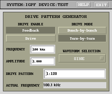 The EPICS control panel for the drive generator is shown on the right. The
 DRIVE ENABLE control selects between two possible DAC signal sources: feedback filter output and the drive generator. The DRIVE MODE selector switches between bunch-by-bunch and turn-by-turn regimes. WAVEFORM SELECTION menu offers four choices: sine, square, sawtooth and arbitrary signals. For the first three signals FREQUENCY and AMPLITUDE controls define the overall signal parameters. The desired frequency is adjusted to produce perfectly periodical waveforms (integer number of periods within one record length). True generated frequency is computed and displayed in the ACTUAL FREQUENCY field.
DRIVE PATTERN is a string input field that allows specification of the bunch-by-bunch enable pattern. The syntactic structure of this field allows three types of elements: single bunch number, range, range with a step. Individual elements should be separated by spaces. Single bunch number element is an integer in the range from 1 to h. A range is specified as start:stop. Range can wrap around, that is if stop is smaller than start, the range covers 1:stop start:h. To specify a range with a step use start:step:stop construct. For example, drive pattern of 2:2:h 1:10 13 includes all even bunches, range from 1 to 10, and bunch 13.
When WAVEFORM SELECTION field is set to ARB, EPICS waveform PV IGPF:{DEV}:DRIVE:ARB ({DEV} is the iGp device name, TEST by default) is used as the drive signal. The waveform has 49152 elements, but in the turn-by-turn mode only the first 12288 are used. Element values must be limited to the range [-256…255].
Usage examples
In this section I will demonstrate the drive generator usage with several examples using Photon Factory numerology: RF frequency of 500.1 MHz and harmonic number of 312.
All bunches, bunch-by-bunch, sinewave
| Parameter | Setting |
|---|---|
| Drive mode | Bunch-by-bunch |
| Waveform selection | Sine |
| Frequency | 1949 kHz |
| Amplitude | 1.0 |
| Drive pattern | “1:312” |
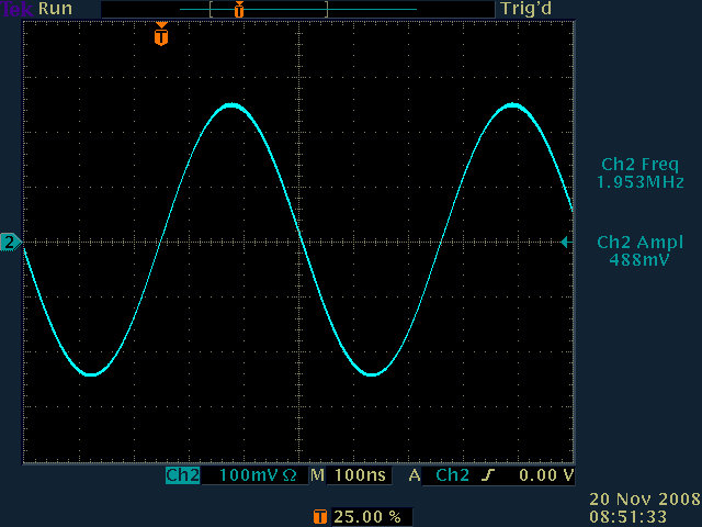
Frequency resolution in this case is fbin=500.1 MHz/49152=10.17 kHz. Actual frequency is then set to 192×fbin or 1953.5 kHz. The output signal at 1.9535 MHz and 490 mVpp is shown in the scope snapshot.
Single bunch, bunch-by-bunch, sinewave
| Parameter | Setting |
|---|---|
| Drive mode | Bunch-by-bunch |
| Waveform selection | Sine |
| Frequency | 1949 kHz |
| Amplitude | 1.0 |
| Drive pattern | “1” |
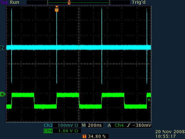
The scope snapshot here shows the DAC output as channel 2 and the fiducial signal as channel 4. The scope is triggered on the fiducial signal. Note that in this configuration the waveform memory is wasted. Only 1/312 of all samples is actually used. Switching to the turn-by-turn mode will produce identical kick sequence, but provide much higher frequency resolution.
A group of bunches, bunch-by-bunch, sinewave
| Parameter | Setting |
|---|---|
| Drive mode | Bunch-by-bunch |
| Waveform selection | Sine |
| Frequency | 1949 kHz |
| Amplitude | 1.0 |
| Drive pattern | “1:234” |
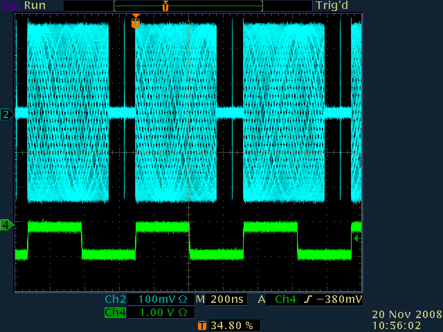
For this example I've enabled drive on the three quarters of the bunches. A single acquisition scope snapshot is illustrated.
"Camshaft" pattern, bunch-by-bunch, sinewave
| Parameter | Setting |
|---|---|
| Drive mode | Bunch-by-bunch |
| Waveform selection | Sine |
| Frequency | 1949 kHz |
| Amplitude | 1.0 |
| Drive pattern | “1:234 280” |
In this case to the previous example a single bunch within the gap has been added.
All bunches, turn-by-turn, sinewave
| Parameter | Setting |
|---|---|
| Drive mode | Turn-by-turn |
| Waveform selection | Sine |
| Frequency | 100 kHz |
| Amplitude | 1.0 |
| Drive pattern | “1:312” |
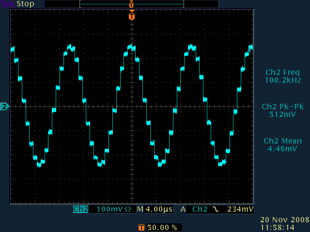
In this mode the frequency resolution is 500.1(nbps)MHz/312/12288=130 Hz. Generated actual frequency is only 50 Hz away from the setpoint. Further improvement in frequency resolution can be achieved by using downsampling.
All bunches, turn-by-turn, square wave
| Parameter | Setting |
|---|---|
| Drive mode | Turn-by-turn |
| Waveform selection | Square |
| Frequency | 100 kHz |
| Amplitude | 1.0 |
| Drive pattern | “1:312” |
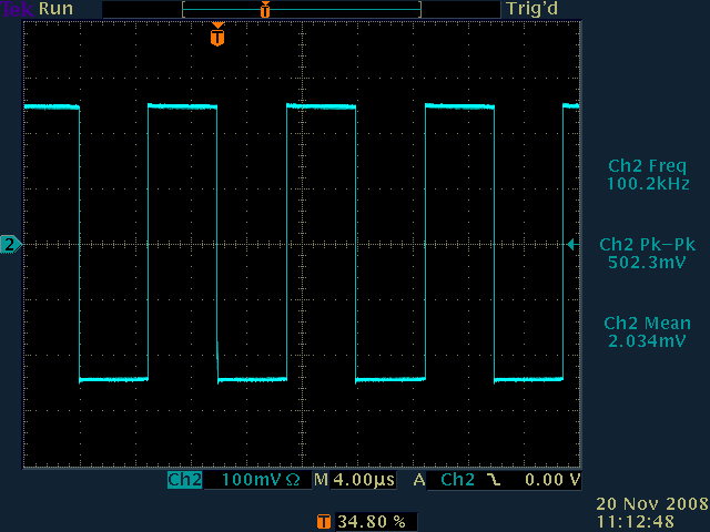
Square waves are often useful to adjust and verify the back-end high-power chain (amplifiers, filters, circulators, kickers). Observing transitions on the kicker load monitor we see the step response of the back-end.
All bunches, turn-by-turn, sawtooth
| Parameter | Setting |
|---|---|
| Drive mode | Turn-by-turn |
| Waveform selection | Sawtooth |
| Frequency | 100 kHz |
| Amplitude | 1.0 |
| Drive pattern | “1:312” |
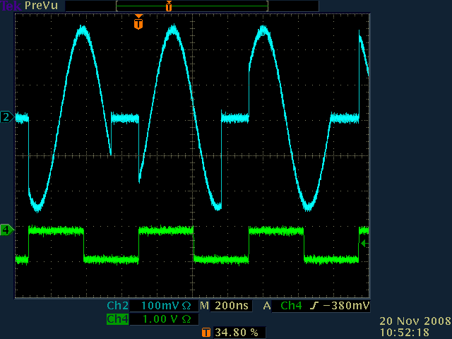
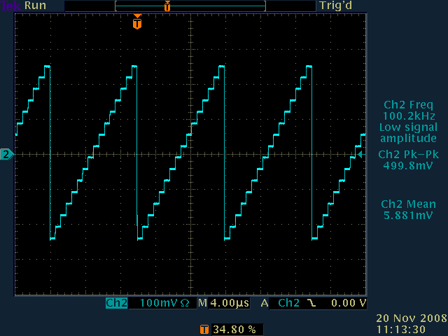
The scope snapshot shows the sawtooth drive in the turn-by-turn mode.
All bunches, bunch-by-bunch, arbitrary
| Parameter | Setting |
|---|---|
| Drive mode | Bunch-by-bunch |
| Waveform selection | Arb |
| Drive pattern | “1:312” |
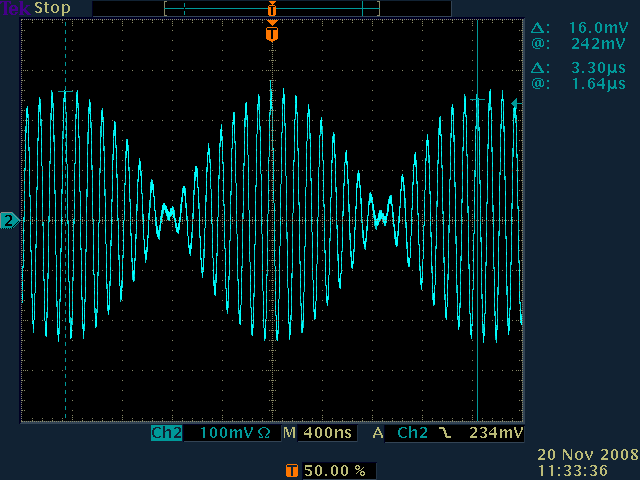
To illustrate the arbitrary waveform functionality I have generated an amplitude modulated signal. Carrier frequency is 10 MHz, modulation is at 300 kHz. To generate and load the waveform I used the following two Matlab commands:
t=[0:49151]/500.1e6;
lcaPut('IGPF:TEST:DRIVE:ARB', floor(255*sin(2*pi*10e6*t).*sin(2*pi*.3e6*t)));
This code snippet uses labCA channel access interface for Matlab. Similar command sequences can be used in Scilab or GNU Octave. Clearly, other methods of waveform generation are also possible.
One useful application of the arbitrary waveform mode is to generate pseudo-random noise signals. Matlab command
lcaPut('IGPF:TEST:DRIVE:ARB', floor(512*rand(1, 49152)-256));
sets up the generator for white-noise excitation. Many techniques exist for frequency-shaping the noise signals.
Dmitry Teytelman 2008/11/20 13:50
