Table of Contents
Longitudinal Feedback Timing Procedure
The process of adjusting longitudinal feedback settings for optimal front-end beam signal detection and best back-end performance is historically called “feedback timing”. In this application note I will present a step-by-step procedure for timing the longitudinal feedback system based on an iGp/iGp12 baseband processors and FBE/FBE-LT front/back units. In the text below, iGp will refer to either iGp or iGp12 and FBE to either FBE or FBE-LT variant.
In this process we are trying to achieve several goals:
- Adjust ADC sampling clock relative to the beam signal;
- Adjust front-end carrier phase to achieve phase detection;
- Adjust DAC clock to optimize kick signal for the right bunch;
- Adjust back-end carrier phase to maximize the kick voltage.
Note that there is certain symmetry in this procedure - we are adjusting one clock and one carrier phase in both front and back-ends.
Some of the steps below are only needed during initial installation or after hardware reconfiguration, e.g. cable/attenuator/amplifier replacement or software/firmware/gateware upgrade. Such steps will be presented in italic text.
Several steps in procedure below can be automated by using sweep shell script. References to usage examples are included for each of these steps.
Machine setup
 As the initial configuration I will assume that iGp/FBE have been installed and connected to BPM signal, RF reference, fiducial, and the power amplifier and that signal levels have been properly selected. Before filling the ring make sure that you have the feedback hardware powered and that you can control system settings from the EPICS panels. It is best to let the FBE warm up for at least two hours. With FBE-LT, set up temperature control as described in the user manual and let the temperatures equalize for several hours.
Before injecting any beam in the ring, turn off the feedback on the top-level EPICS panel. Also, turn off the front-end phase servo loop (Front/back-end control panel under Setup→Devices→GPIO).
For this procedure we need a single bucket in the accelerator filled to the nominal per bunch current. It is not important which bucket is filled, as long as its number is known.
Note: on iGp EPICS panels bunch numbering starts from 1.
Step 1: Rough front-end timing
At this point the setting of the front-end phase shifter is arbitrary, so the mixer can be anywhere in the range from amplitude to phase detection. We would like to adjust the phase shifter for amplitude detection and then roughly time the ADC. This is necessarily an iterative process where we alternate between adjusting the ADC delay and the phase shifter setting. Typically one can see the effect of the phase shifter adjustment pretty much at any ADC delay - so we start from phase shifter adjustment.
- Move the phase shifter in steps of 100 (each step of the phase shifter DAC is ~0.25 degrees) until the single-bunch spike amplitude is maximized (sign is unimportant) on the mean plot in the waveform window. This step can be automated by the sweep script as shown here.
- Roughly time the front-end by moving the ADC delay in steps of 500 ps and observing the response in the waveform window. We are looking for maximum mean amplitude of the single-bunch spike. This step can also be automated.
Repeat the two steps above after the first pass.
Step 2: Adjusting fiducial delay
 At this point we need to adjust
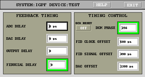
 FIDUCIAL DELAY in the timing panel. To do so, determine which bucket is seen as filled on the waveform plots (Nwfm). Let's suppose the actual filled bucket number is Nact. Then FIDUCIAL DELAY must be increased by (Nwfm-Nact)/2. The resultant value for FIDUCIAL DELAY should be less than h/2 where h is the harmonic number. If the value is larger than or equal to h/2, subtract h/2 from it. This adjustment has granularity of two buckets. If the result is one bucket off, increase FIDUCIAL SIGNAL OFFSET by one RF period.
Step 3: Setting front-end for phase detection
Now we need to set up the front-end for phase detection. Adjust the front-end phase shifter so that the mean of the filled bunch is the same as that of the empty buckets. Here is an example how this step can be simplified by using the sweep script.
Step 4: Determining the synchrotron frequency
As a starting point one should use the nominal value known from previous measurement and/or machine parameters. After steps 1 and 2 it might be possible to see the synchrotron peak in the averaged spectrum plot. Use RECORD LENGTH and REC. DOWNSAMPLE settings to extend data acquisition time span and, therefore, achieve finer frequency resolution.
Step 5: Turn on the drive
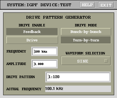
 Now we need to drive the beam at the synchrotron frequency. Open the drive panel and set it up as follows:
- Set
DRIVE ENABLEto “DRIVE” - Set
DRIVE MODEto “Turn-by-turn” - Type synchrotron requency determined in step 3 in the
FREQUENCYfield - Set
WAVEFORM SELECTIONto “Sine” - Set
AMPLITUDEto 1 - Set
DRIVE PATTERNto all bunches. For example, if harmonic number is 232, type “1:232”
Step 6: Optimizing back-end carrier phase
At this point in the procedure you should observe some beam motion in the filled bucket, driven by the excitation we have applied. It might be useful to fine-tune the drive frequency a bit to improve the response. We are looking at the RMS plot on the waveform panel - the RMS of the filled bunch should be visibly above that of the empty buckets. Adjust back-end phase shifter to maximize that RMS value. Sweep script example can be found here.
Step 7: Determining back-end bucket offset
At this point in the process the system should be exciting the beam strongly at the synchrotron frequency. The difference between the excited and the normal states can be checked by flipping DRIVE ENABLE back to “FEEDBACK” for a few seconds.
Now we need to determine which channel in the back-end is actually kicking the beam. To do that we perform a binary search. Initially we are driving all buckets, say 1:232. Now we will change the DRIVE PATTERN to only drive one half of the previous range, that is 1:116. If the beam is still driven, then continue dividing the current range, otherwise switch to the other half, i.e. 117:232. Using this method after a few steps (8 for 232) you will identify a single bucket Nm which, when enabled in the DRIVE PATTERN, excites the beam. Now, adjust OUTPUT DELAY on the timing panel by Nm-Nact, where Nact is the actual filled bucket number. If the delta is negative, add harmonic number. After this adjustment, setting the DRIVE PATTERN to Nact should drive the beam.
Step 8: DAC clock timing
Next step is to time the DAC output relative to the beam. We will start from maximizing the excitation response while adjusting the DAC DELAY on the timing panel. The sweep script is very useful during this step - see an example. Reasonable step size during this adjustment is 100 ps. During this adjustment it might be necessary to lower the drive amplitude if the front-end is being saturated - typically manifested by extended flat-top response. The drive amplitude should be lowered until the RMS at the top of the sweep starts to drop.
Note that maximizing the response might require changes to the OUTPUT DELAY value. If in your sweep the RMS continues to increase at the endpoint (0 or TRF), you need to extend the sweep further. Back-end timing adjustment has two controls“ DAC DELAY with the range of one RF period and 10 ps step and OUTPUT DELAY with the range of one turn and one RF period step. Take a system with 2 ns RF period as an example. Then setting of OUTPUT DELAY of N and DAC DELAY of 1990 ps is 10 ps away from OUTPUT DELAY of N+1 and DAC DELAY of 0 ps.
Once the RMS response is maximized, we can fine-tune the timing. This method has been proposed by Alessandro Drago of LNF-INFN. The idea is to equalize the parasitic excitation of the neighboring buckets. Set the AMPLITUDE on the drive panel to 1. Then set the DRIVE PATTERN to two values: first to Nact-1 and then to Nact+1. Note the RMS levels at each of these settings. If the reading at Nact-1 is larger, increase DAC DELAY in small (10 ps) steps. Otherwise, reduce DAC DELAY. The goal is to equalize the coupling to the two buckets adjacent to the driven one.
Step 9: Final front-end timing
Finally we will optimize the front-end timing. This is done by adjusting the ADC DELAY setting on the timing panel to maximize the RMS motion of the filled bunch. Prior to the adjustment the drive amplitude needs to be reduced until the RMS signal starts to drop, thus avoiding saturation.
Front-end design is typically quite wideband, so there might be a significant flat-top portion in the ADC response vs. clock timing. Optimal timing in this case is midway between the points where the response starts to drop off.
A sweep script usage example is available for automating this step.
The End
Congratulations - you have completed the longitudinal feedback phasing and timing procedure! Don't forget to save the system configuration!
Dmitry Teytelman 2010/12/14 10:50